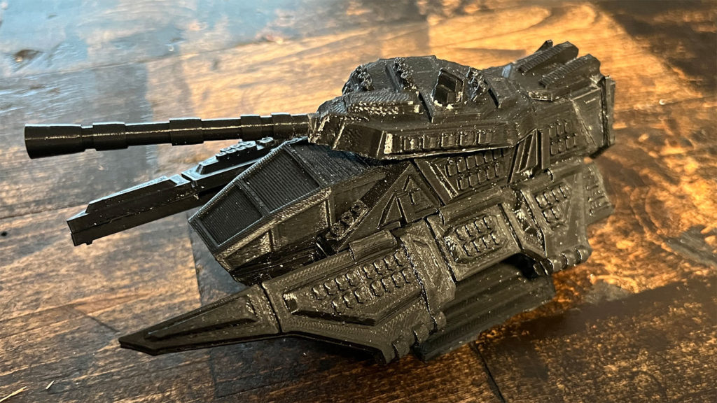
Griffin Hover Tank
General Assembly Advice
Several of the steps require gluing areas of the miniature which had attached support material. In order to get a stronger bond, sand down these areas with 220 grit sand paper. Only use super glue for assembly. Plastic glues do not work on PLA.
File Downloads
Print off one of the each file in the above archive. Files in the No Support folder should have supports turned off for the print. Files in the Support folder require support to print correct and files in the support-brim-raft folder require either a brim or a raft to print correctly. Each file should already be in the correct orientation for printing. Files marked as left or right refer to the left or ride side of the vehicle if you were standing behind the vehicle.
Step 1 – Attach Wing Pegs
Locate the bottom of the wings and insert a peg into each of the peg holes. The four wing peg STL files are identical and it does not matter where each peg goes.
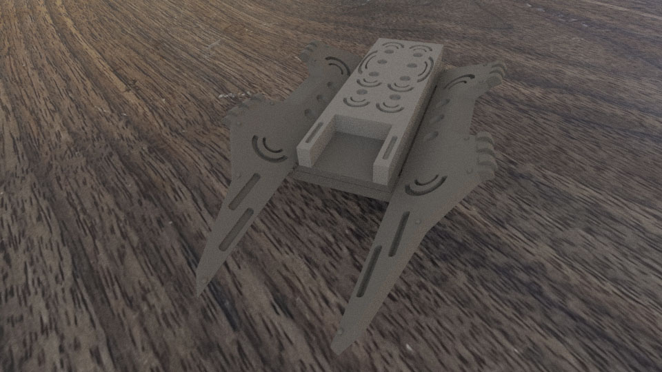
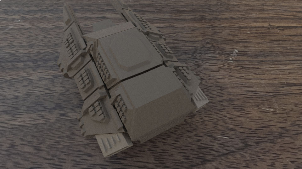
Step 2 – Prepare Tank Body
Locate the top of the tank body and remove the support material. The front of the tank body has a more gentler slope than the back.
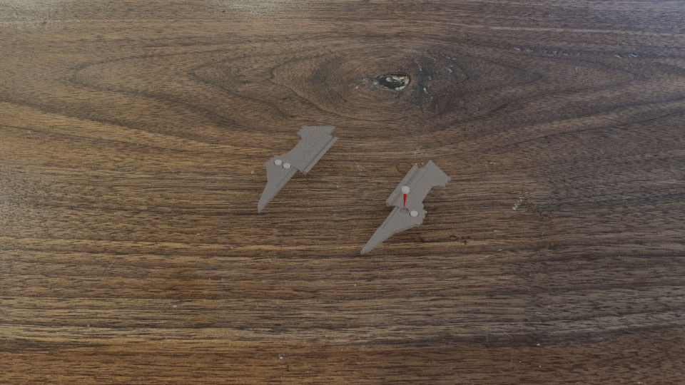
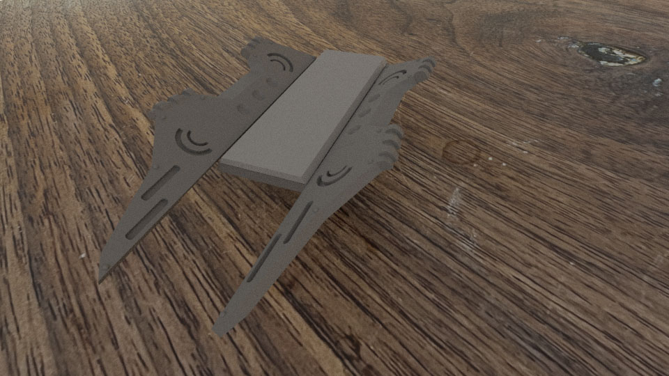
Step 3 – Attach Wings to Tank Body
Flip over the tank body. Apply glue to the inside of the wing’s tab as indicated in the image and attach them in the under body slots as far back as possible.
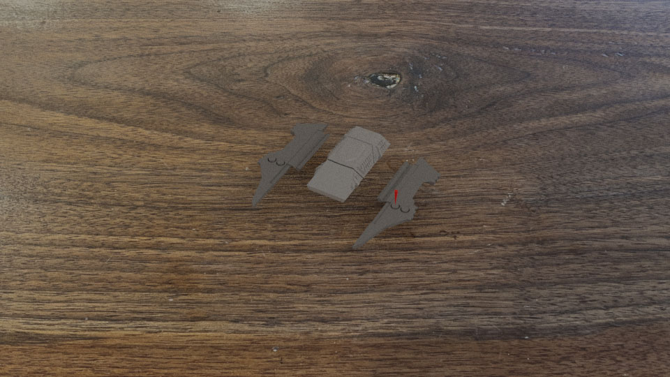
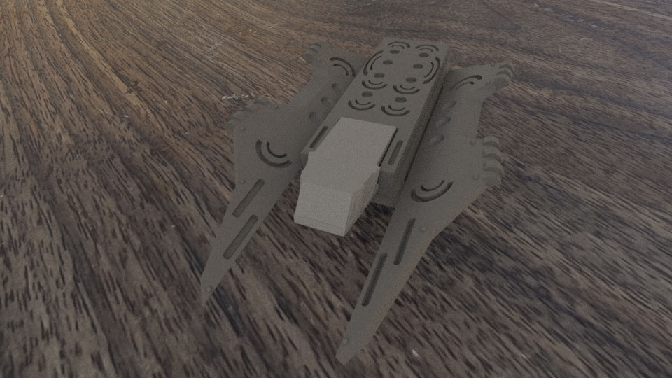
Step 4 – Attach Body Engine Spacer
Glue the body engine spacer to the bottom of the tank body. This piece has a trapezoid shape and glue the piece such that the smaller face is on top. Please note that this piece should be slightly smaller than the distance between the wings.
Step 5 – Attach Lift Engines to Body
Glue the lift engines to the bottom of the tank body. The notch should face towards the front of the tank body
Step 6 – Attach Cockpit Bottom
Locate the bottom of the cockpit and glue it in place in the lift engine notch. Please note that the bottom of the cockpit is slanted. It will slightly rise out of the lift engines.
Step 7 – Attach the Tops of the Wings
Flip the tank back over and glue the tops of the wings onto the model. The wing pegs should get the top of the wing very close to the final position, but some small adjustments will be required.
Step 8 – Assembly Wing Engines
Each of the wings has an engine and each engine is made from two parts. The bottom part, which is the thinner part has one flat edge and angled engine. When this piece is faced downward, its angled edge will align with the angled side of the top of the engine. Glue each of these engines together as shown.
Step 9 – Attach Wing Engines
Glue the wing engines to the back of the wing has shown. The angle of the engine should match the angle of the back of the wing and the bottom of the engine should attach cleanly to the bottom of the wing such that it sits between the two rivets on the bottom.
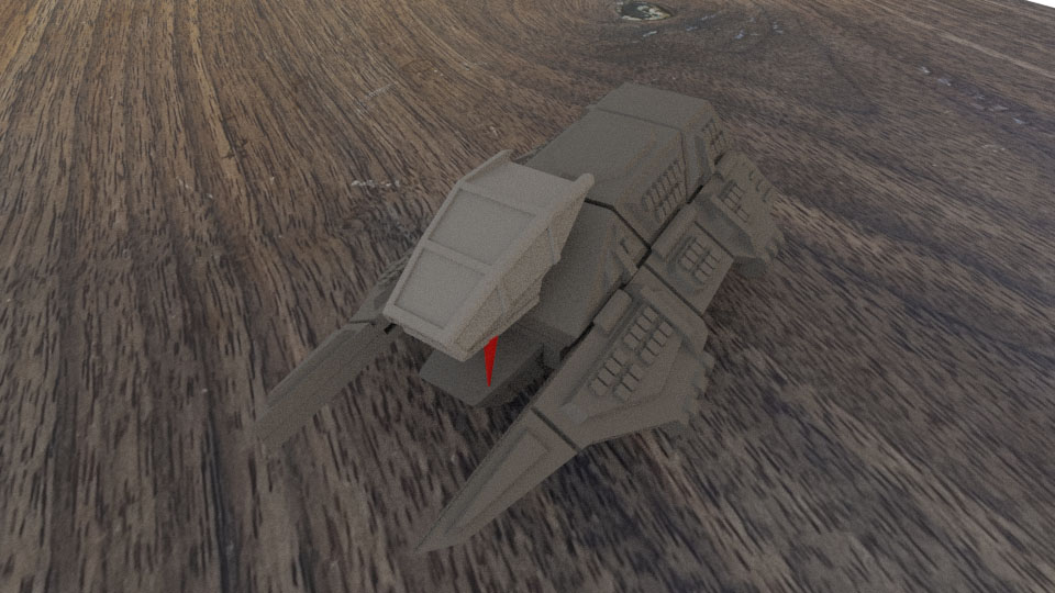
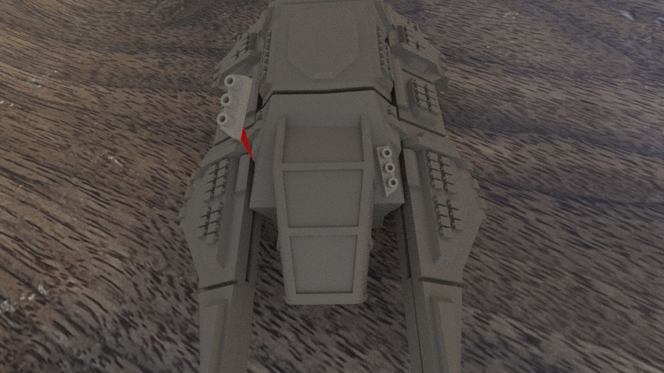
Step 10 – Attach the Cockpit Top
Glue the top of the cockpit to the front of the front of the tank. It should line up very closely with the bottom of the cockpit.
Step 11 – Attach Main Engines
Remove the support from the main engines and glue them to the back of the miniature. The engines should align with the back of the tank.
Step 12 – Attach Top Engine Cooling
Glue the top engine cooling fins to the tank. It should rest in the middle of the tank and the back of the cooling fins should align with the back of the engine shroud.
Step 13 – Attach Side Engine Cooling Ribs
Glue each of the side cooling ribs to the engine as shown.
Step 14 – Attach Rear Engine Access Doors
Glue the two rear engine access doors to the back of the lift engines as shown. These two pieces should be spaced equally out across this area of the miniature.
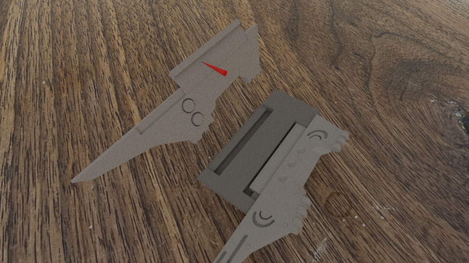
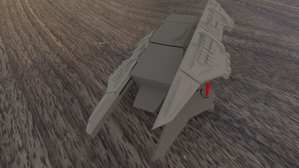
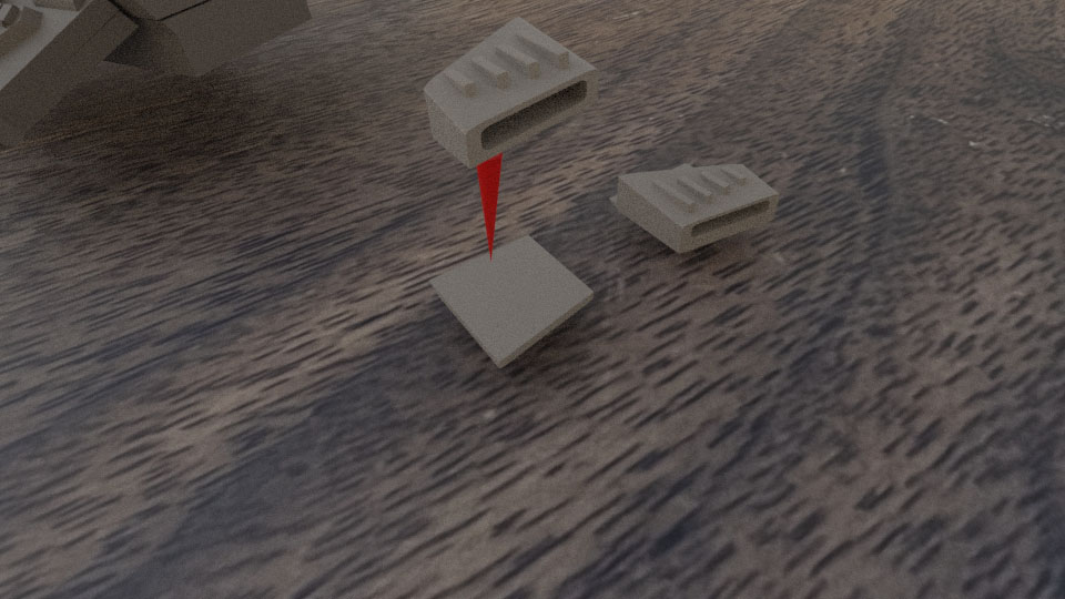
Step 15 – Attach Forward Smoke Launchers
Glue the two forward smoke launchers on either side of the cockpit. Each smoke launcher has a pointed side and this should face down towards the bottom of the tank. The launchers themselves should face slightly outward, away from the cockpit.
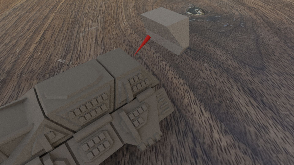
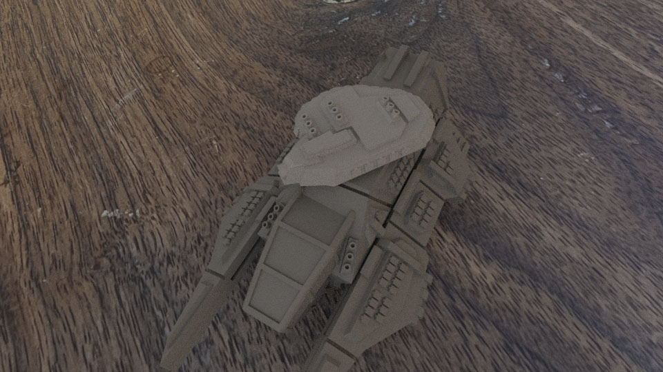
Step 16 – Glue on the Main Turret
Glue the turret body to the top of the tank. Angle it in which ever direction looks cool. It should be glued onto the raised armor panel on the top of the tank body.
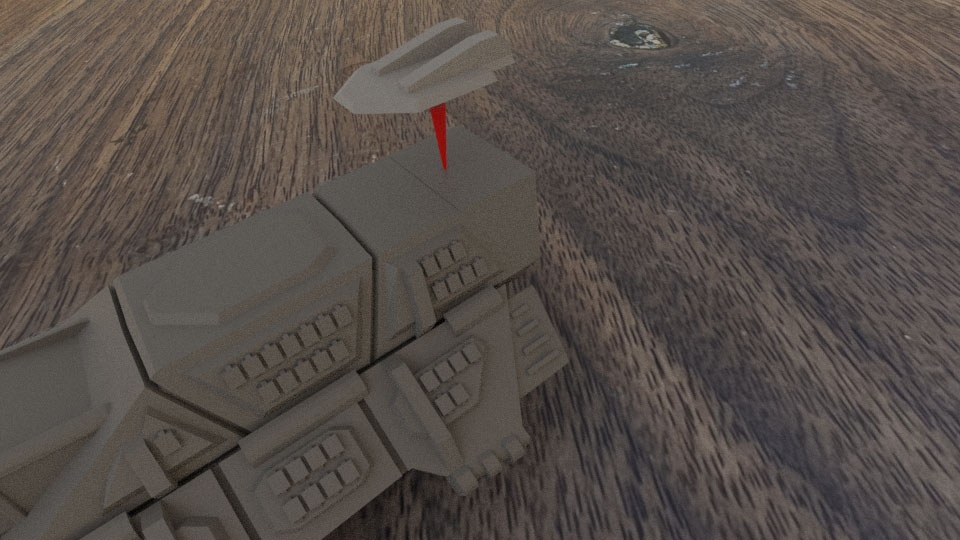
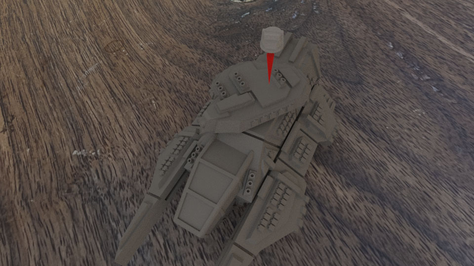
Step 17 – Attach the Commander’s Viewer
Locate and attach the Tank Commander’s Viewer and glue it to the top of the turret.
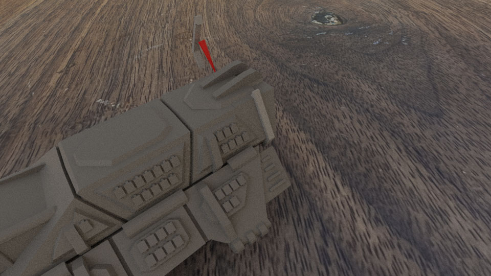
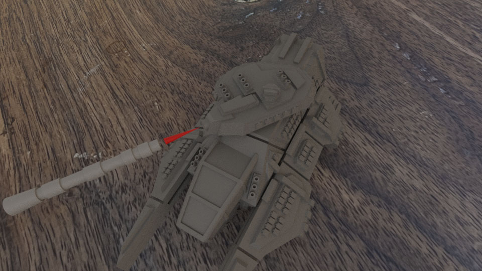
Step 18 – Attach the Main Cannon
Attach the main cannon to the front of the turret.
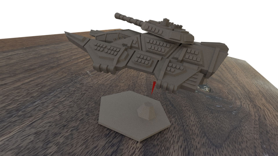
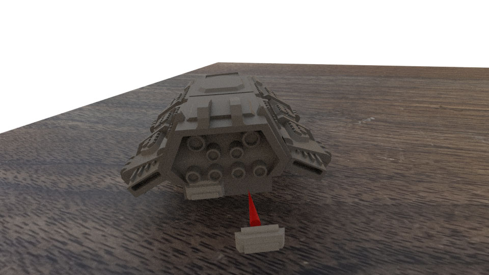
Step 19 – Attach the Tank to the Hex Stand
Finally, glue the tank to the hex stand. You may want to wait until after painting to perform this step. Also, you might get creative with options like magnets to attach the tank to the stand.